2026-08-14: wireless control
Many years ago (back in 2021) I bought a decommissioned flip-dot panel BUSE BS 210.C from the Prague public transport company. The original plan was to use it in a robotics club, but in the end that never happened.
There is no public documentation for the panel, and BUSE Blansko (the manufacturer) did not respond to a request for documentation.
First attempts
Hardware
The panel is covered at the back by a sheet-metal plate with four “locks” of a similar construction to those on electrical cabinets. So the first step was clear – design and print a key1.
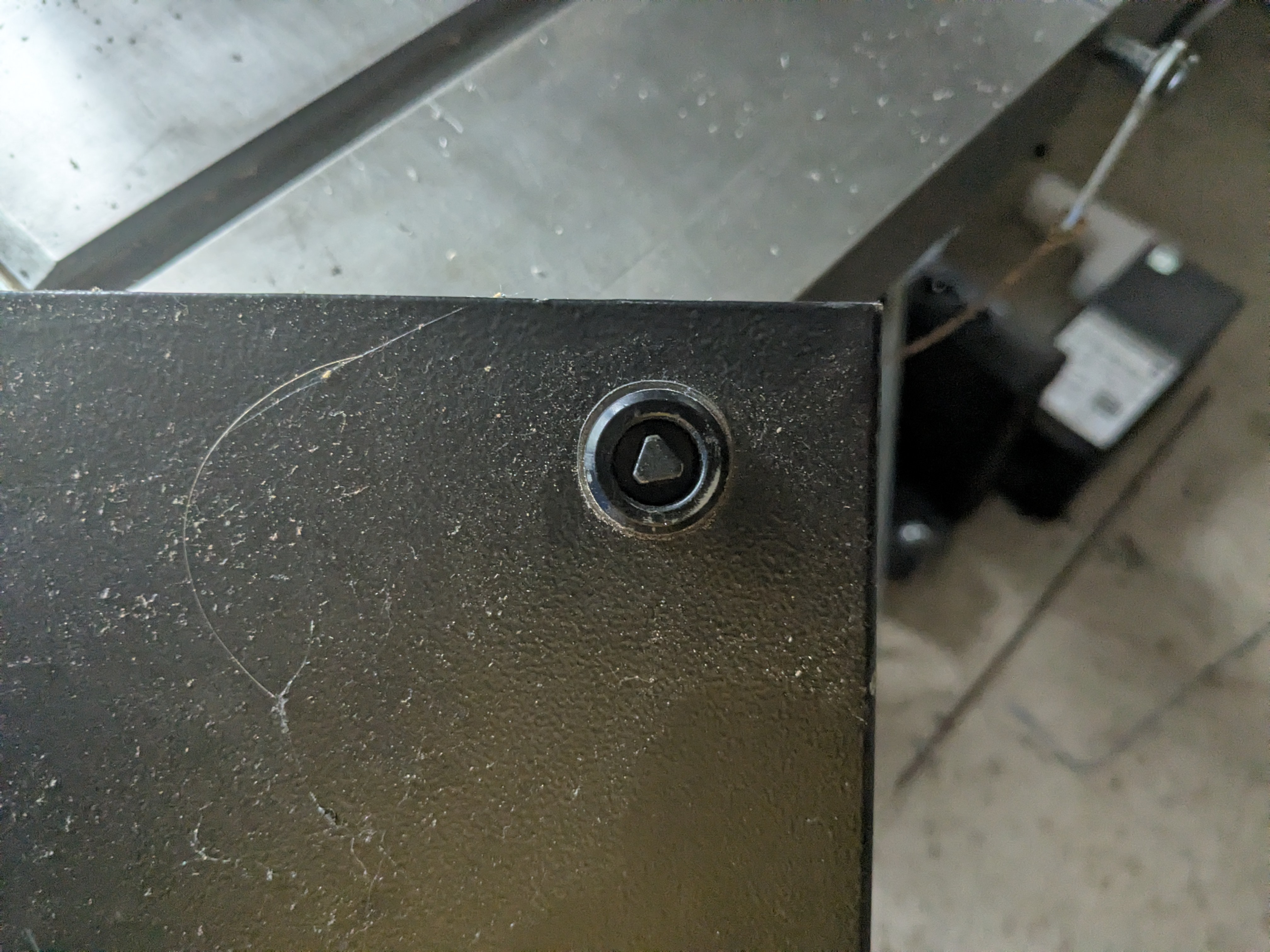
One of the locks on the panel’s rear cover.
Once it is open, we are greeted by the mainboard, which is really nicely made, and the main terminal block.
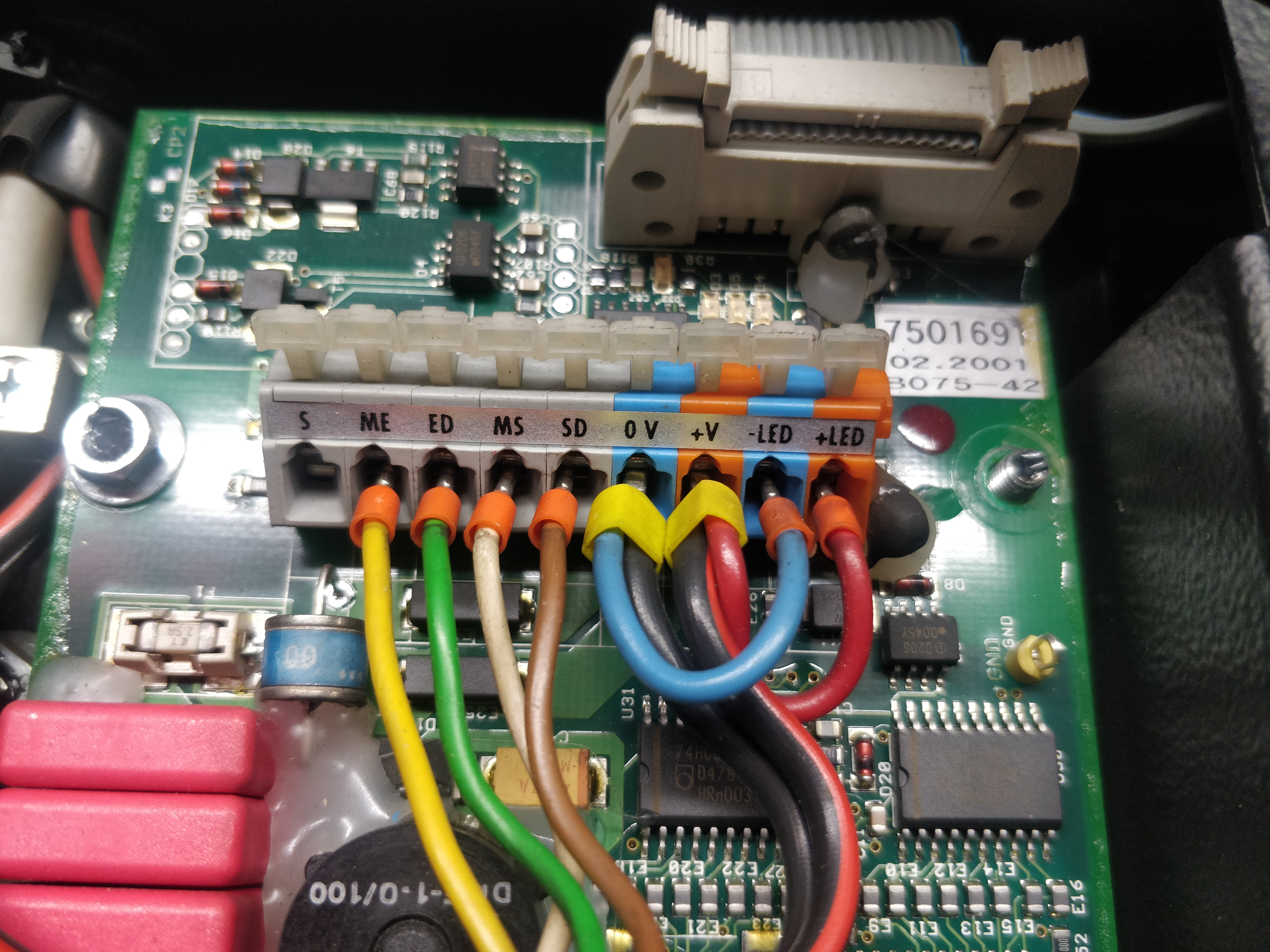
The terminal block inside the panel with the original cable still connected.
| Terminal | Meaning |
|---|---|
| S | ? |
| ME | 0V (Vss), zero potential |
| ED | device response |
| MS | 0V (Vss), zero potential |
| SD | command to the device |
| 0V | 0V (Vss), zero potential |
| +V | 24V (Vcc) |
| -LED | 0V (Vss), zero potential |
| +LED | 24V (Vcc) |
IBIS
It was to be expected that the panel implements the IBIS protocol for communication. IBIS is essentially a simple UART serial protocol running at 1200 baud (specifically 1200 7E2). The bus is always under the control of the on-board computer, which sends commands and possibly expects a response. Many commands are non-addressed and effectively behave as a broadcast (all devices react to them). It is, however, designed for buses, meaning a 24V on-board network. The data lines are 24V too, so they cannot be connected directly to a computer’s ordinary RS232/UART interface.
IBIS refers to the individual commands as telegrams2. In the specification a telegram is designated by a number (e.g. 001, also often written as DS001). Physically, however, the commands are often represented by one or two characters. So DS001 means the physically sent command l for line. So line 1001 will mean the telegram l1001. The individual texts (e.g. the name of a stop) are, however, stored directly on the individual devices, so in normal operation only short messages are sent, such as a change of line, destination stop and so on.
| IBIS command | Meaning | Example |
|---|---|---|
l{:>03} |
line | l176 |
zC{:>04} |
destination stop | zC1005 |
zD{:>04} |
next stop (2nd line) | zD1006 |
aA{:>02}text |
print text on the device with a specific address | aA01Dobry den |
uHHMM |
set the time HH:MM |
u1205 |
e{:>06} |
fare zone | e000001 |
a{:>02} |
status report of the device at the address; the normal state is a0 |
a01 |
aV{:>02} |
query the version of the device at the address | aV01 |
I built the converter to TTL logic from two MOSFETs (for transmitting) and a resistor divider (for receiving). Since those were two rather random transistors and the resistor values were pretty random as well, signal integrity was nothing to write home about.
Using pyFIS I managed to send a few basic IBIS telegrams. For example, I iterated through the line values (the l command) and thereby discovered some interesting DPP lines :)
However, to my great disappointment, the panel did not react to commands such as aA, so it was not possible to print custom text.
On the Internet I discovered that there are programs GBUSE0.exe and GBUSE1.exe, supplied by the manufacturer and used precisely for configuring the content3. When I managed to find it in one of the groups, it became clear that the author of the configuration has the option to disable/enable individual commands. So DPP decided not to allow aA4 (and zM did not work either).
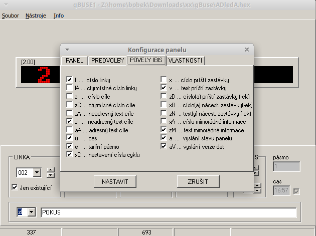
Screenshot of GBUSE.
There is also another manufacturer application, BSLoader. It allows content to be uploaded into the panel and also service tasks such as a panel test to be performed. However, the application refused to work with the panel for me. Which was partly down to my efforts to run it under wine, and partly to the signal integrity of my crappy converter.
Somewhere around here I shelved the project …
Second attempt
In 2026 I revived the project, for two reasons – first, I came across a description of the service commands; second, the kids and I came up with the idea of putting the panel on the fence and sending words of wisdom to it for the delight of passers-by5.
IBIS converter
After the (inglorious) experience, I redid the converter and used 74HC14 Schmitt inverters as the basis.
Converter from 24V IBIS to TTL (or 3.3V) with a 74HC14.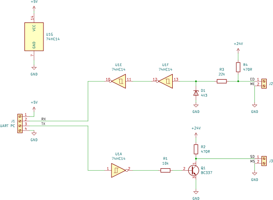
BSLoader started working without any problems too.
BSLoader and aA
First I tried uploading a new configuration that would allow aA and similar commands to be sent. That worked, and printing really did function. But it was not possible to influence the formatting in any way. The text was always printed in a large font. I did find a description of the MNEMO language, which serves to describe formatting, but it only works for creating stored content. It cannot be used for IBIS commands.
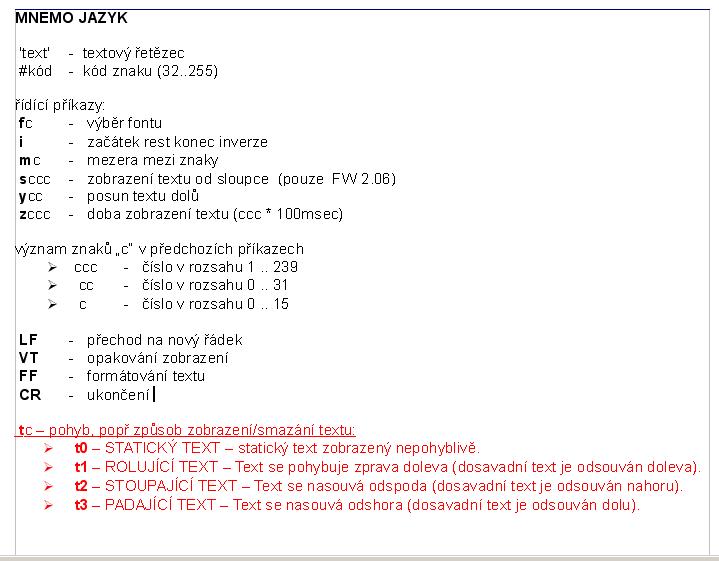
The MNEMO language
Custom control electronics
At this point I wanted to give up on using the original BUSE electronics and simply design my own controller that would be connected in place of the original board. I even came across a very similar project https://github.com/mcer12/Flippity210 . The original board of course also has a nicely made driver section…
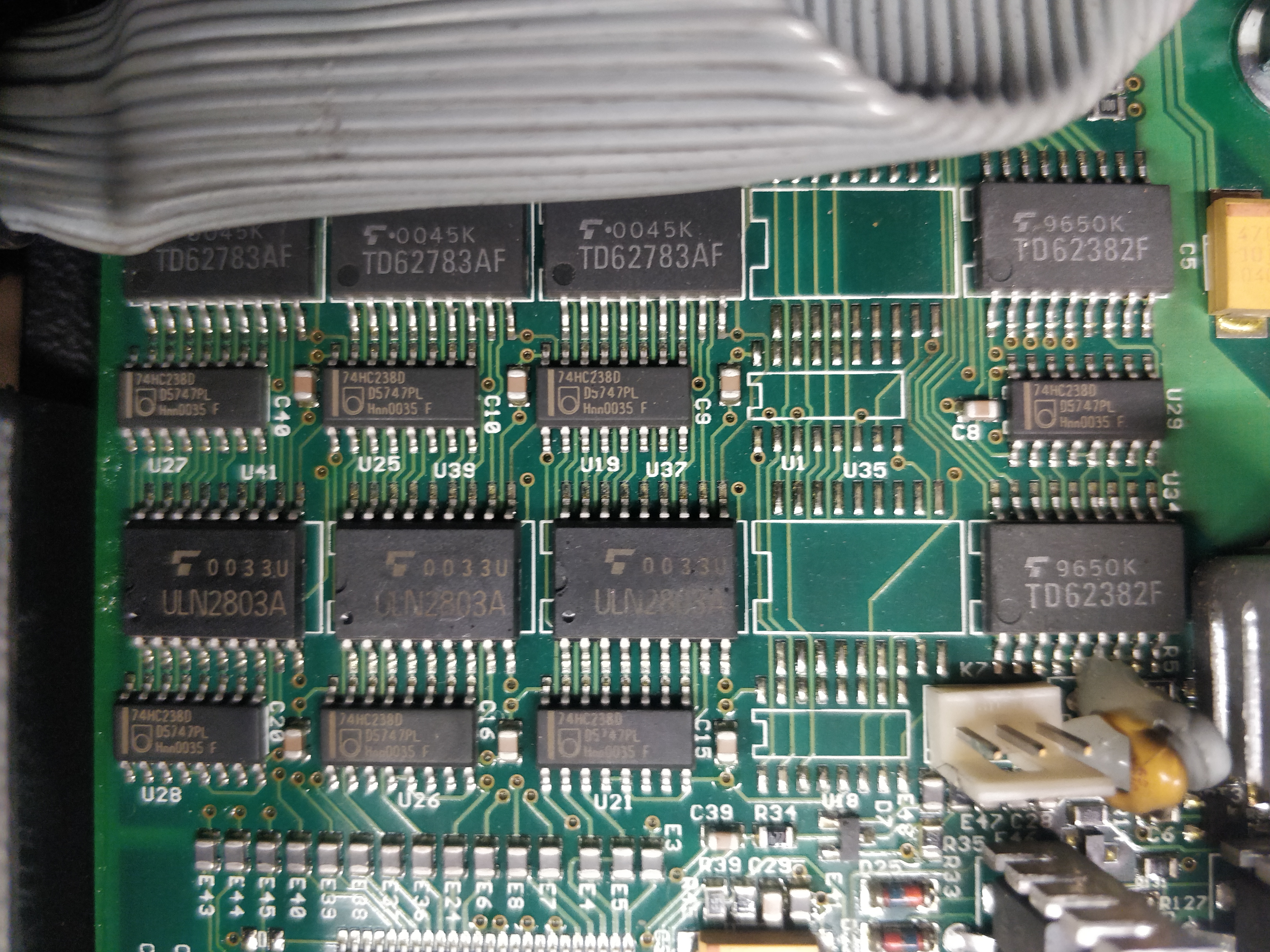
The original board, the driver section.
It really seemed to me like a terrible waste to simply throw it away. I even considered the option of desoldering the original processor and bringing out a connector from its GPIO, into which I would plug my own.
Custom firmware for the original control unit
I went back to the original processor for a while. It is a TMP96C141BF, a 16-bit processor from Toshiba6, nowadays no longer recommended for new designs. Toshiba supplied an IDE for it that ran only on Windows, but the compiler and linker were programs usable from the command line.
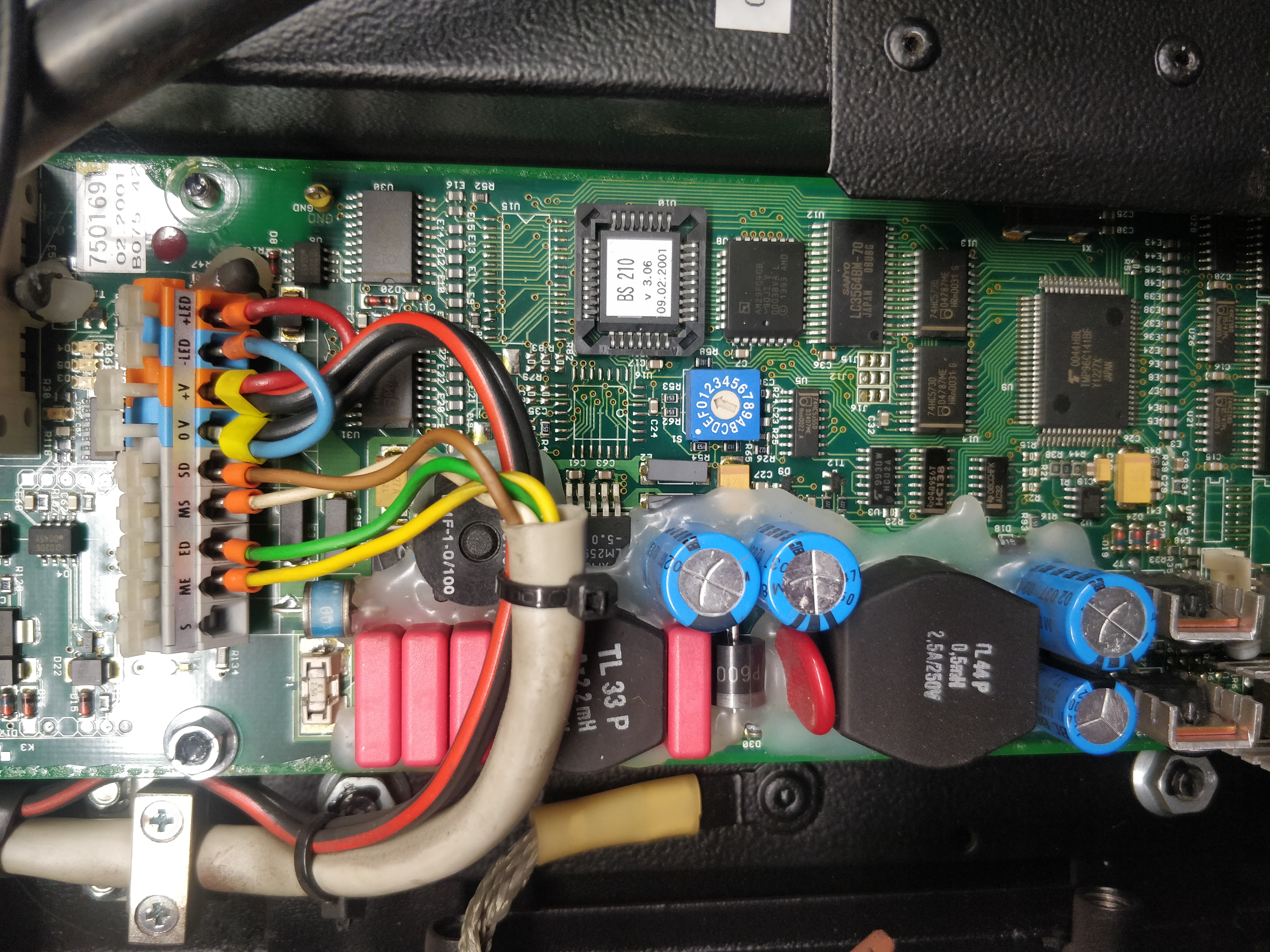
Mainly the control section of the original board. The EEPROM in its socket and the processor are clearly visible.
The EEPROM (AT28C64B) with the original firmware is helpfully placed in a socket. At the same time Anthropic made Fable5 available again, and I also found a copy of the original IDE and helper programs from Toshiba on the Internets . So I read out the original program and had Fable5 write its own, one that would implement just a single command – drawing a bitmap.
To my great delight it really did work out, and I now have working firmware that allows fast bitmap rendering on the panel. Converting text to a bitmap and so on is now taken care of by the source (a Python script, in my case).
Wireless panel control
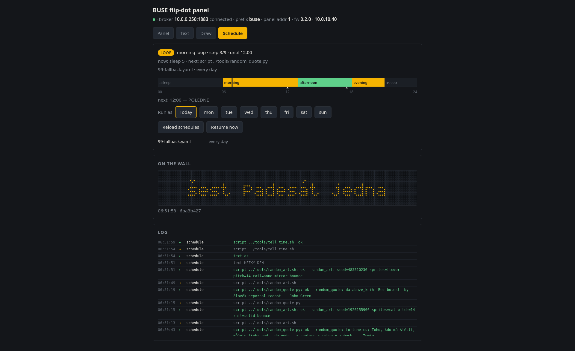
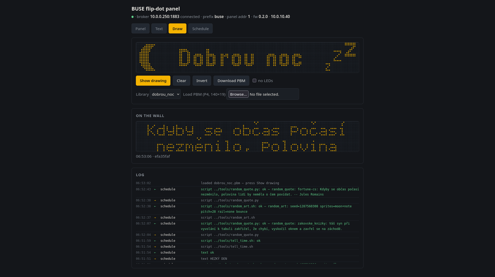
Combining the things described above with an ESP32 module produced a wirelessly controlled panel. The ESP32 firmware is connected to an MQTT broker, which is how commands for rendering text or a bitmap reach it. The panel also sends back the bitmap it has just sent over the serial interface. That allows a web application not only to control the panel, but also to display its state.
Activity schedule on the panel, generative graphics. Activity schedule on the panel, current time. Making a bitmap by hand or uploading a PBM.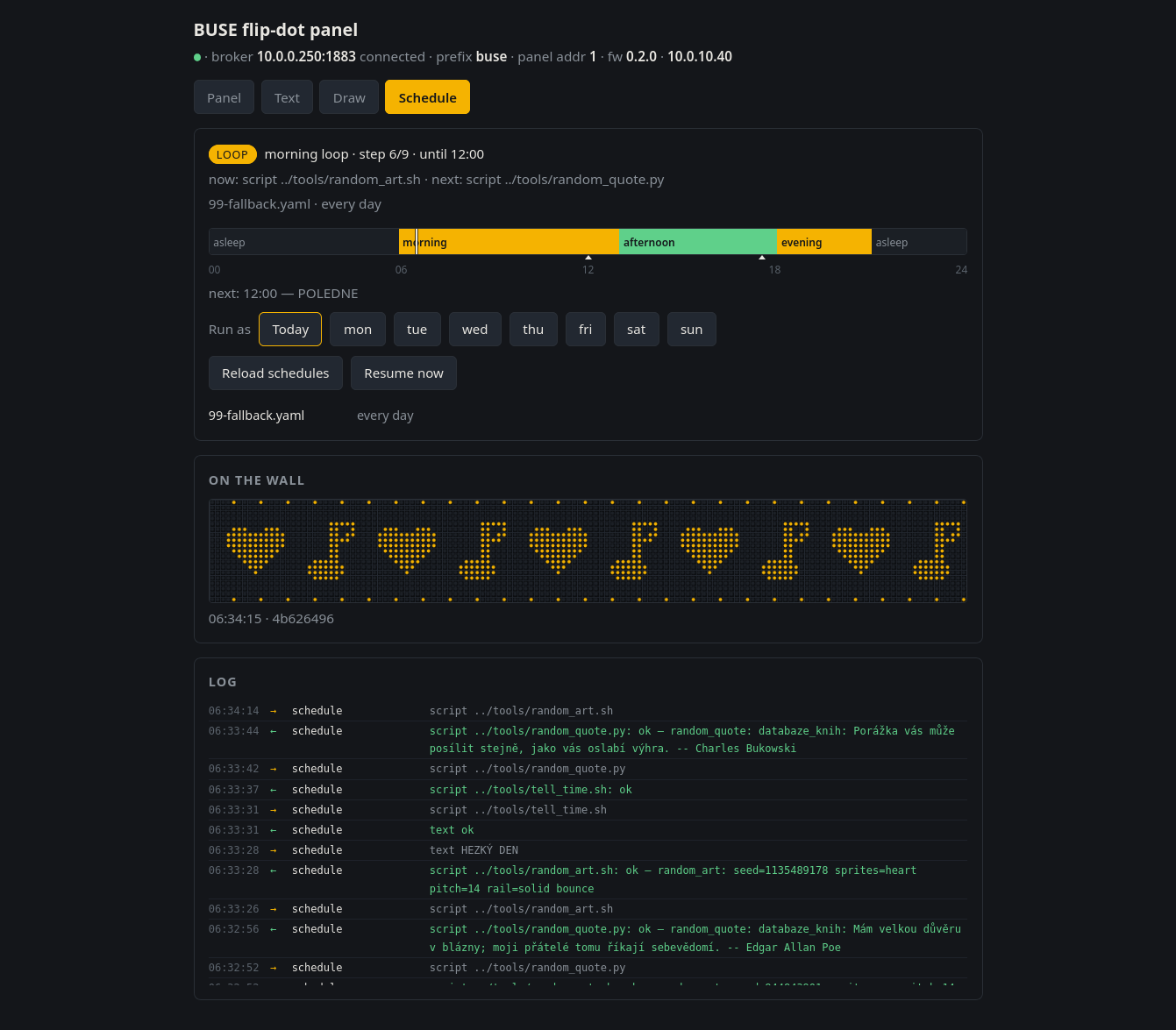
-
To be found at https://github.com/bobek/flipdot_revival/tree/main/case_key ↩︎
-
The specification can be found at https://knowhow.vdv.de/documents/300/ ↩︎
-
GBUSE0is for flip-dot displays, whereasGBUSE1is for pure LED panels. ↩︎ -
For which they actually deserve praise, because commands that are not needed are not enabled and no confused texts end up on the panels by mistake. ↩︎
-
A bit like https://www.novinky.cz/clanek/internet-a-pc-ai-umelecka-instalace-bavi-cestujici-na-prazskem-nadrazi-40548600 ↩︎
-
https://toshiba.semicon-storage.com/ap-en/semiconductor/product/microcontrollers/detail.TMP96C141BFG.html ↩︎