Kids wanted a working traffic light for one of their games. I took it as a good reason to hide in the workshop and produced one showed on the video below.
This is super-simple project, why to write a post about it, you may ask? Initial temptation was to grab some small MCU (or even Arduino as that is basically ready to use for such project). But I have opted for old-fashion way without using an MCU and rather some combination logic.

As you can see, there are 3 main sections:
- shared output section with transistors driving the color LEDs
- single
NE555generating pulses for yellow warning mode - another
NE555driving counter to run a “program” for a full cycle
You can think about the CD4017 counter as being a step counter (program counter), which points into lookup table to resolve into desired LEDs state. Lookup table is realized with set of signal diodes, which just pass 1 when needed (and not allow current to pass back to gate and/or drive other LEDs). Length of the step is determined by NE555 output frequency.
Programming table is simple:
| Step counter / Pin active | Active LEDs |
|---|---|
Q0 |
red |
Q1 |
red |
Q2 |
red |
Q3 |
red |
Q4 |
red + yellow |
Q5 |
green |
Q6 |
green |
Q7 |
green |
Q8 |
green |
Q9 |
yellow |
Wiring of diodes directly follows the table above and connects counter output pins Q* to appropriate transistors’ base to drive LEDs. I have not designed PCB at the end as construction was simple and one-off.
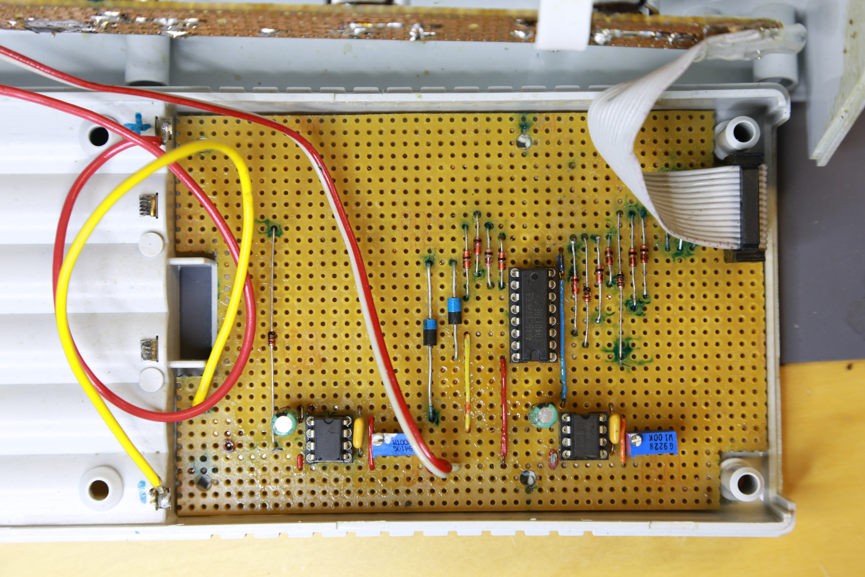
All components on a perfboard

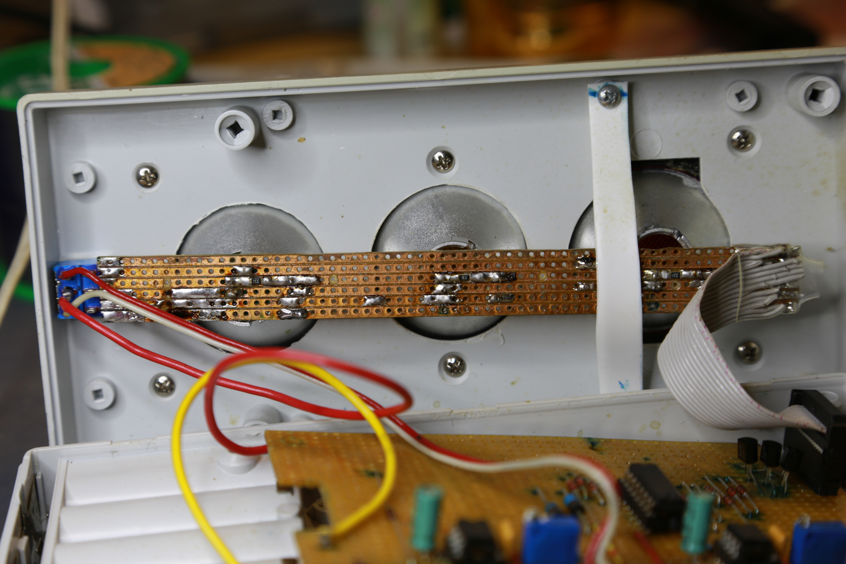
Bottom of a perfboard
LEDs assembly